Networking Fundamentals For DevOps
We all use Internet, right? But how does this Internet actually work? Are you interested to learn about internet and networking? In this blog, we will…

On this page (17)
- What is a Network ?
- Types of Networks
- Network Components
- 1\. Switch:-
- 2\. Router:-
- 3\. Modem:-
- 4\. Hub:-
- 5\. NIC:-
- 6\. Bridge:-
- What is Protocol ?
- IP Address and its Types and Classes
- Topologies
- Network Models
- DNS (Domain Name System)
- Want to master DNS ? get to know the ins and out of DNS in [this course](https://www.nslookup.io/dns-course/) developed by [Ruurtjan Pul](https://twitter.com/Ruurtjan)
- Subnet Mask
- Network Utilities
We all use Internet, right? But how does this Internet actually work? Are you interested to learn about internet and networking?
In this blog, we will learn about the network fundamentals and many more. So, let's get started ! 🔗
What is a Network ? #
When two or more computers and computing devices connected together with each other through communication channels, such as cables or wireless media and sharing some files, then it is called a Network.
A network is used to:
-
Allow the connected devices to communicate with each other.
-
Enable multiple users to share devices over the network, such as music and video servers, printers and scanners.
The Internet is the largest network in the world and can be called "the network of networks". (remember this word 🙂)
Types of Networks #
There are different types of network. But the main two are LAN and WAN 👉
-
LAN (Local Area Network) - interconnects computer within a limited area, such as residences, schools. e.g:- Wi-Fi, Ethernet
-
MAN(Metropolitan area network) - used in metropolitan area (cities).
-
WAN (Wide Area Network) - extends LAN over a large geographic area. e.g:- optical fiber cable
-
SONET (Synchronous Optical Network) - used in submarine.
Network Components #
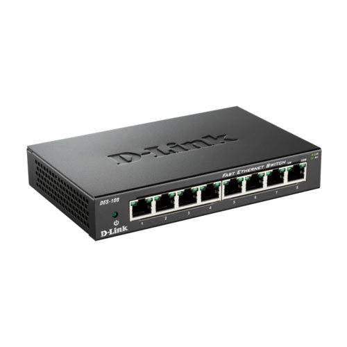
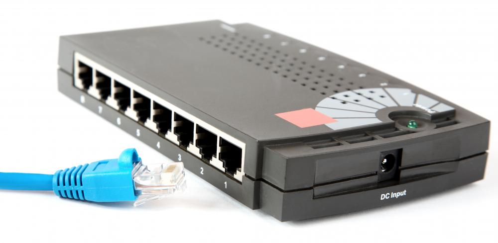
1. Switch:- #
It is a device which connects two or more computers.
Suppose we are four friends, and we want to play a game like counterstrike together in LAN, then what exactly we will do? We can connect with Wi-Fi, or we can use a device called Switch to connect with each other physically in a home, and then we can play. So a Switch is nothing but a device used to connect devices locally.
When we use switch, it actually makes one table inside it is known as MAC address table. So if device A is sending data to device B for the first time, switch will store the MAC address of both A and B. So next time when data is going to transfer between A and B now switch knows the MAC address of both. Now data will directly reach to B device(unicast), not C and D. For the first time switch broadcast the data means data will also reach to C and D but for the next time broadcasting will not happen.
There are many types of switches -
-
Unmanaged switch - In this switch if we send some data from device A to device B then the data will also reach to device C and D which is not so good. In our house, we use this type of switch concept e.g:- Extension board
-
Managed switch - VLAN concept is used in this switch, and it has many features. It is used in company and in industrial level.
If you want to learn more about Switch, you can search about KVM, POE and Smart switches.
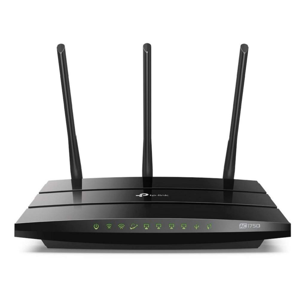
2. Router:- #
It is a device which is actually used to connect one network with another.
Suppose, ten computers are connected via a switch, and it's a LAN network. But if we want to connect this LAN network with another LAN network, then Router will help to connect them. The device which is used in our home for broadband connection, we think that this is a Router, but actually this is not a Router. This device is a combo of router, modem and small switches called ADSL (Asymmetric Digital Subscriber Line) provided by our ISP (Internet Service Provider).
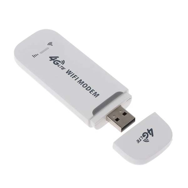
3. Modem:- #
It is also a device used for modulation and Demodulation.
When we get any type of signals, they are actually coming to your device in the form of Analog signal, but your computer only understand digital signals(0 and 1). So we can't send analog signals directly to the system. So here Modem is used for converting your signals analog to digital and vice-versa. For this reason, ISP put down this modem functionality in your ADSL.
4. Hub:- #
It is just a power extension dummy device that just broadcast the signals to it's connected computers.
Suppose there are 4 computers(A, B, C, D) connected via a Hub. Now If computer A is sending some data to computer B then those data will also reach to C and D computer. So Hub always broadcast because it works on signal. So if you send any signal it will reach to everyone connected with that Hub. It does not store any MAC address of the devices. **So this is the main difference between Hub and Switch.**Hubs are now largely obsolete, and it replaced by switches which are able to learn MAC address of devices.
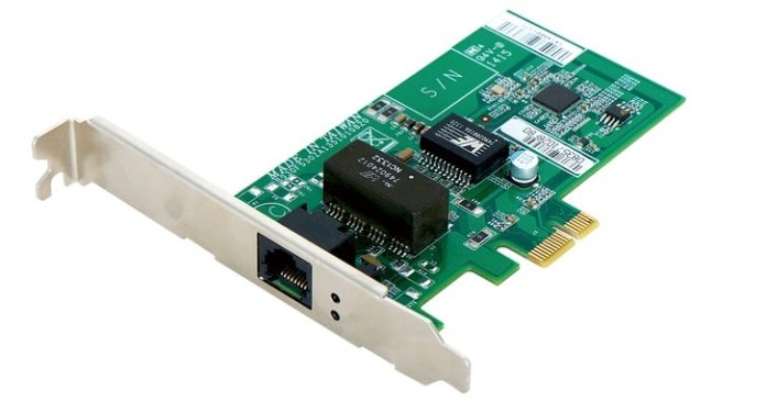
5. NIC:- #
It is known as Network Interface Card which is used to connect your computer with the internet. It is wireless card preinstalled on motherboard now-a-days. It has a MAC(Media Access Control) address.
6. Bridge:- #
It is also a networking device that connects multiple LANs (local area networks) together to form a larger LAN. It reduce the broadcasting part and it store the MAC address of the computer but now this device is also obsoleted and replaced by switch.
What is Protocol ? #
A network protocol is a set of rules which is set up by peoples that determine how a particular data is transmitted between different devices in the same network. e.g:- HTTP, TCP, IP, FTP, SMTP etc.
IP Address and its Types and Classes #
Every device on the internet must have at least one unique network address identifier known as the IP (Internet Protocol) address. This address is essential for routing packets of information through the network. Without our address none can find our location and like that without an IP address a device can't be found on a network.
There are two types of IP addresses - IPv4 and IPv6 (v stands for version)
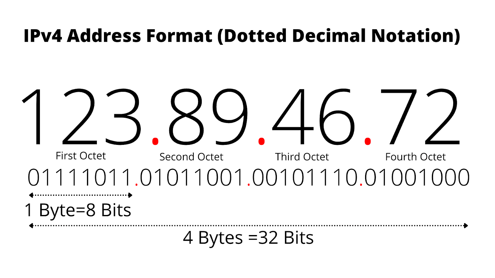
- IPv4
This is a 32 bit IP address, means it contains a combo of 32 (1 and 0's). In this version of IP address there are 4 groups or Octets(8 bits) and each octet is represented by a decimal value in the address. It is easy to remember.
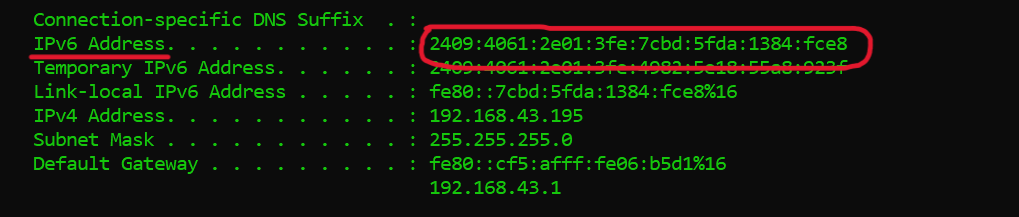
- IPv6
This IP address contain 128 bits. We use IPv6 because we have a shortage of IPv4, almost all IPv4 is used now and this is the reason IPv6 is commonly seen nowadays. This address is represented by a hexadecimal value.
- Classes of IP address (mainly for IPv4) :-
There is an organization called IANA (Internet Assigned Numbers Authority) who divides the IP address into different classes. You have to know about binary to decimal conversion to understand this.
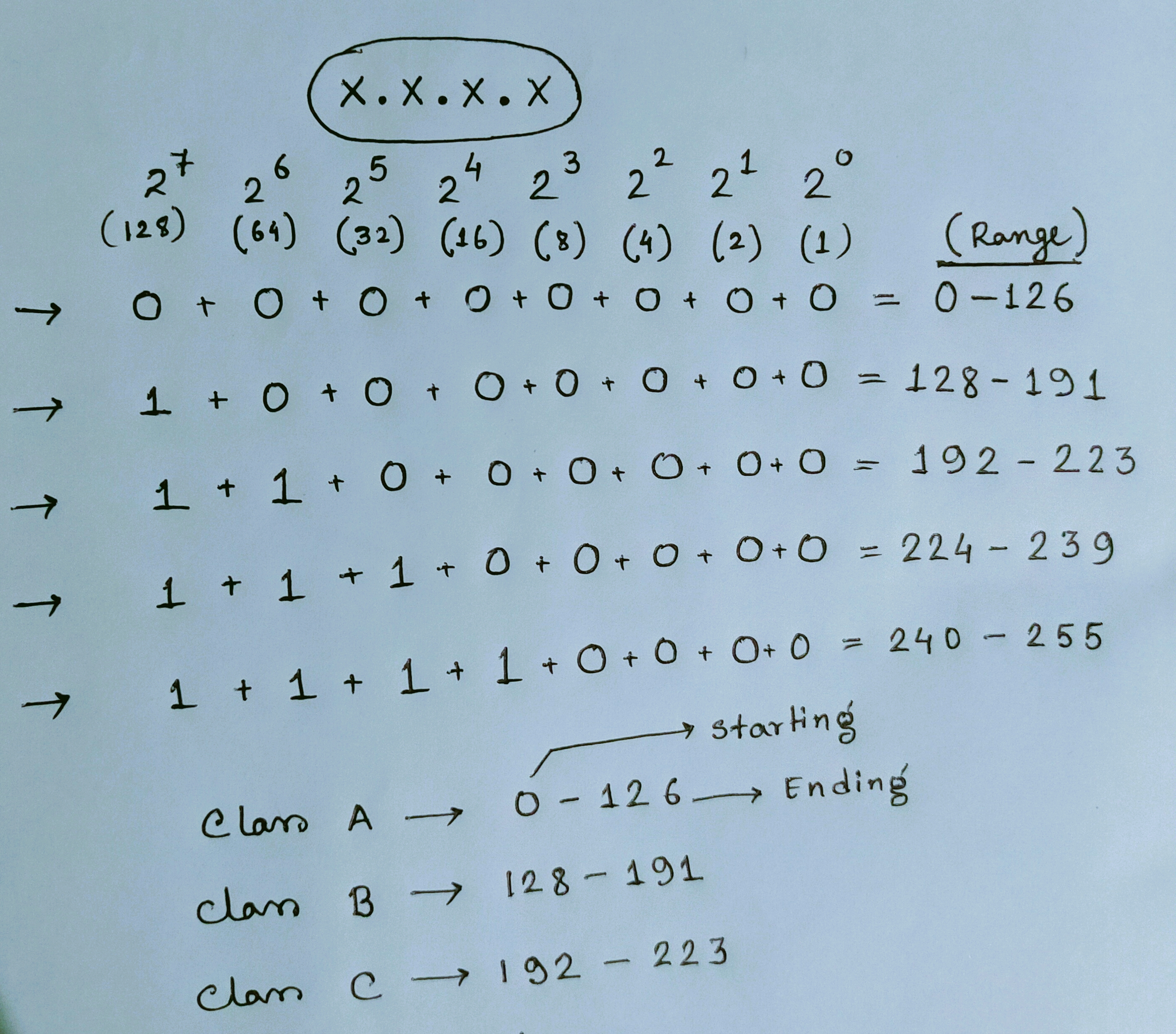
Class D is reserved for multicast groups, and class E is reserved for future use.
Read this carefully --
There are two parts to an IP address - Network ID and Host ID (Any device which gets the IP address is called a Host).
To connect device A with device B we have to check just the network ID only for both the devices. Suppose device A (17.0.0.1) and device B (17.0.4.2), so both are class A IP address because their first octet under the range 0-126. For class A the network ID is first octet and remaining three octets for Host ID and for class B the first two octets are network ID and remaining Host ID and for class C the first three octets are network ID and the last octet is Host ID. So here the net ID of both the device is 17, so they can connect with each other easily and both devices are in a same network. But If the network ID is different, then we have to use a Router to connect them because a Router is used to connect two or more different networks.
Topologies #
A Network Topology is the shape or arrangement of a Network with which computer systems or network devices are connected to each other. Topologies may define both physical and logical aspect of the network. Both logical and physical topologies could be same or different in a same network.
There are different types of Topology -
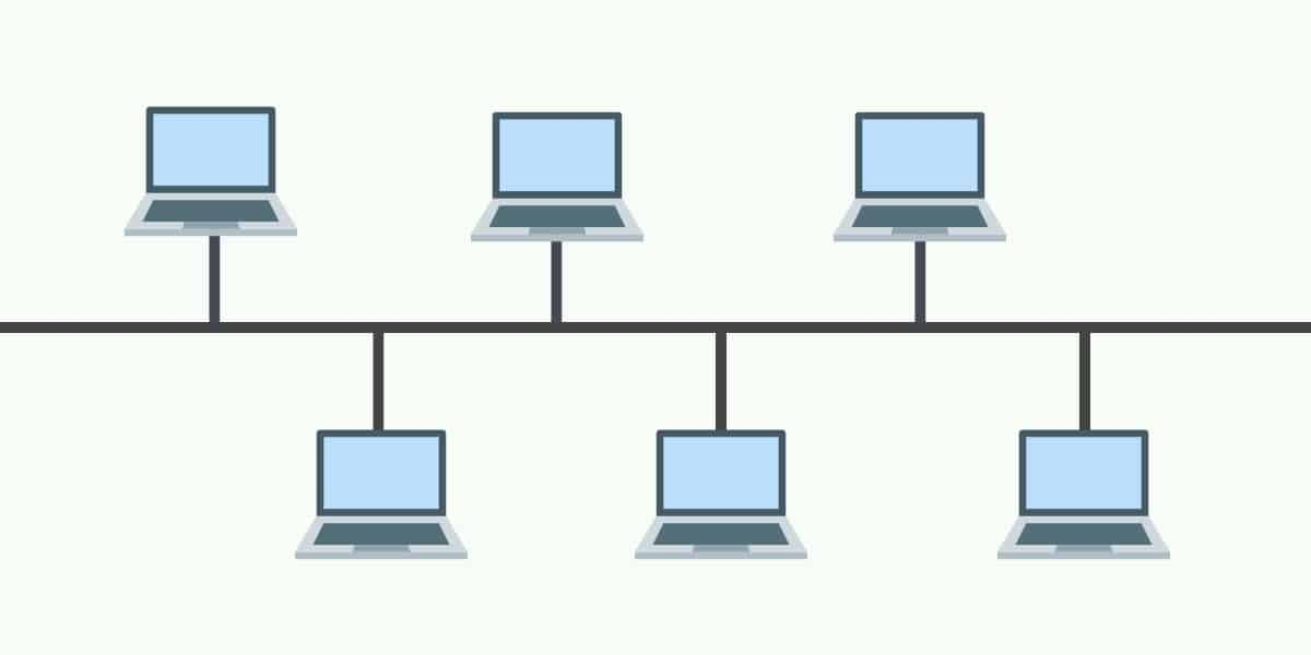
- Bus Topology
In this topology, all devices share a single communication line or cable. For this topology the main problem is for any cause if that cable breaks then the whole network will break down.
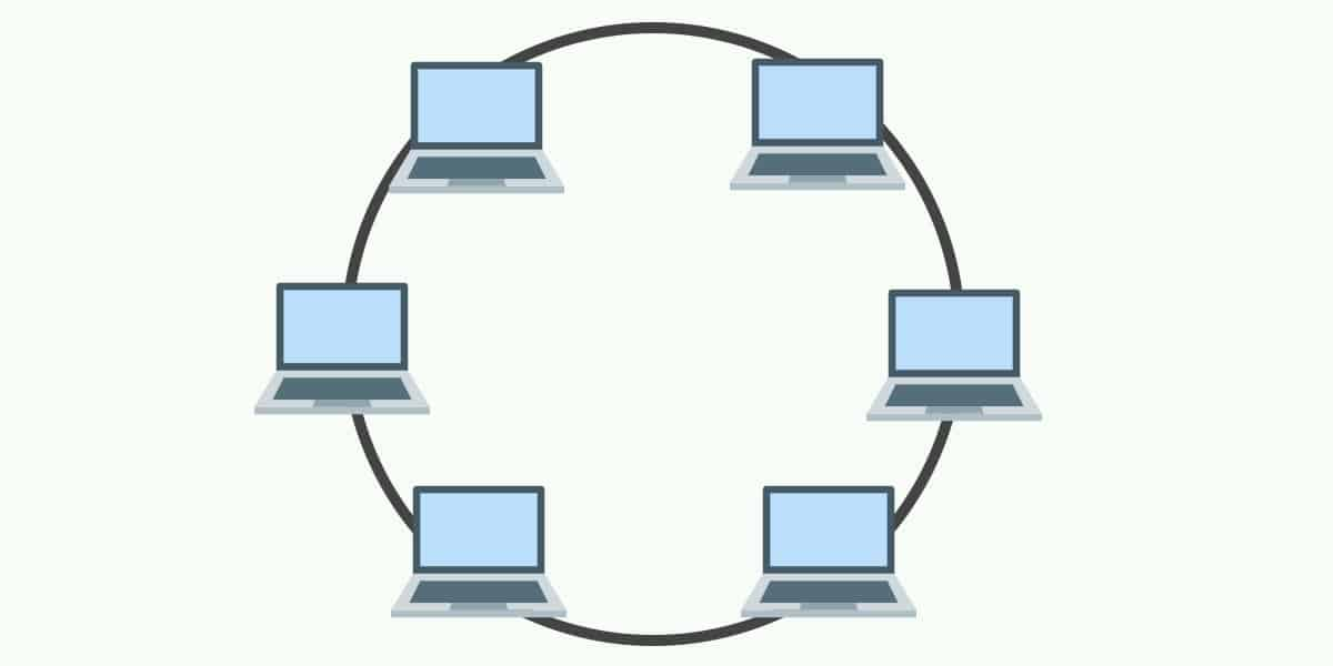
- Ring Topology
In ring topology, each host machine connects to two other machines, creating a circular network structure. For any cause, if any host break down then whole network will break down. Thus, every connection in the ring is a point of failure.
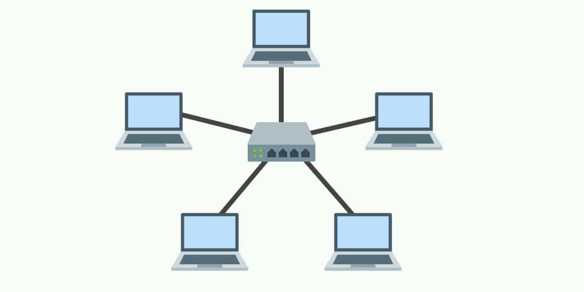
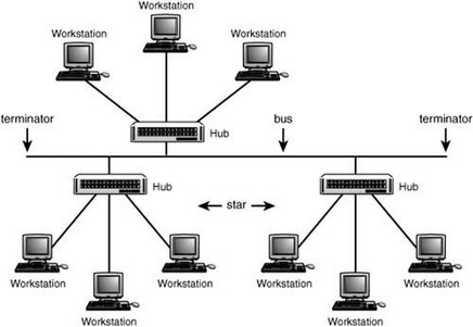
- Star Topology
In Star topology, all hosts are connected to a central device, known as a hub device, using a point-to-point connection. That is, there exists a point to point connection between hosts and hub. If the Hub fails for any cause, then the whole network will be broken.
- Tree Topology
This topology is the combination of Bus and Star Topology. In this topology, each Star topology being connected via a single communication line or cable. This is the most common form of network topology in use presently. The main problem in this topology is if that single cable breaks then the whole network will break down.
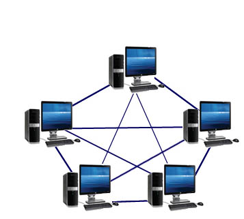
- Mesh Topology
In this topology, each host are interconnected with each other through various redundant connections. It does not contain the switch, hub or any central computer which acts as a central point. The Internet is the main example of Mesh Topology. But the main issue with this network is this topology, networks are very large and very difficult to maintain and manage. If the network is not monitored carefully, then the communication link failure goes undetected.
Network Models #
There are mainly two types of network model -
-
OSI Reference Model
-
TCP/IP Model
-
OSI Reference Model #
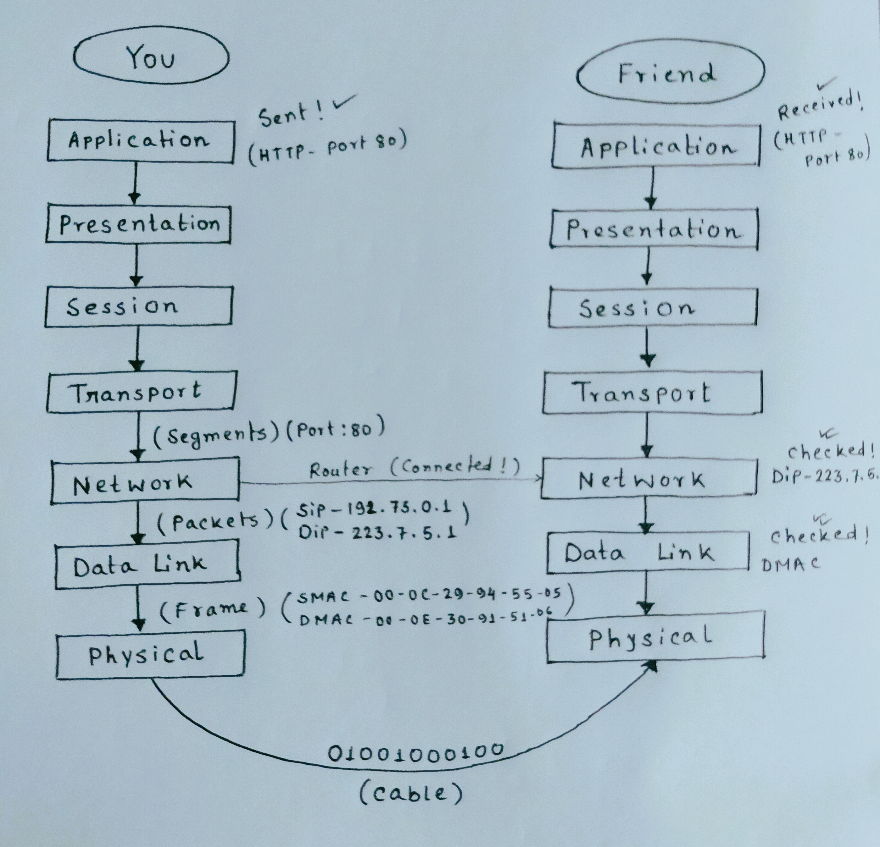
The OSI model (or Open Systems Interconnection Model) is a reference model created by ISO (International Organization for Standardization) which describe how different types of systems communicate together. The OSI model consists of seven different layers that each have its own unique purpose and responsibilities. This is an imaginary model.
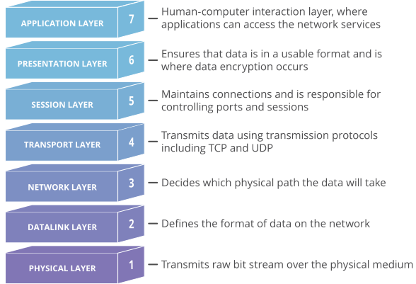
1. Application Layer #
Any software which interacts directly with one human to another comes under Application Layer. e.g :- WhatsApp, Gmail, Web browser etc. Different types of protocol given below is used in Application Layer - (let's discuss some protocol in details)
-
HTTP (Hypertext Transfer Protocol)
It is a client server stateless (means it never stores any data of client)protocol, and it tells us how it request any data from the server and also tells us how the server will send the data back to the client.
-- When a client makes a request - HTTP request
-- When server sends response to client - HTTP response -- Some HTTP methods used to make any request
  GET :- Get some data from server
  POST :- Post some form/data to server
  PUT :- Put some data
  DELETE :- Delete some data in server
-- Status Codes
Status codes are issued by a server in response to a client's request made to the server.
html 1XX - Informational 2XX - Success! 3XX - Redirecting 4XX - Client Error(eg:- 404 not found!) 5XX - Server Error I have said that HTTP is a stateless protocol, means it never store any data of client in server. Then suppose when you will search for the second time amazon.com then it should be logged out from the server, and you have to log in again for second time visit, but you don't. In second time, it's automatically logged in, and you can see all of your saved carts 🛒 and all data. So how it is possible?? Here, cookies comes into the picture.
Cookies is a unique string stored as a file in your browser and when you search for the second time the website you visited previously, cookies which saved in your browser will send the details through HTTP to the server and server will check it and automatically logged you in.
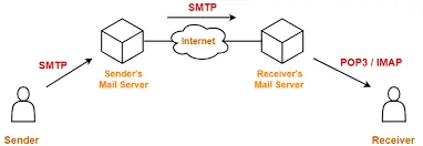
- SMTP/POP (Simple Mail Transfer Protocol and Post Office Protocol)
SMTP is used in sending and receiving any email from senders SMTP server to Receiver's SMTP server
POP is used to download any email from POP server
-
FTP (File Transfer Protocol)
FTP is used to download, upload and transfer files from one host to another host.
2. Presentation Layer #
This layer actually tells about the Format of Data(just remember this 🙂) means when you see a webpage like google.com or YouTube.com, there you can see many videos, images, thumbnail of videos, comments and all. So the presentation layer helps to represent the data of any format.
3. Session Layer #
When the data is moving to Session Layer, so session layer is actually create and maintain the sessions with the time frame. Whenever you open any bank website, it has a time limit. If you are away from your keyboard for some time, then that session will automatically log out. If you are not using your keyboard or mouse pointer or anything, then the session will log out automatically by a session layer algorithm written by the developers. This is the responsibility of Session Layer.
4. Transport Layer #
By this Layer the Data in converted into small segments means this layer divides the data in multiple chunks or parts. This layer is also responsible for sequencing the segment, means it will actually add the serial number on each data segment. Because when the data is travelling from one PC to another PC over the internet, so might be there is a chance that one part/segment of data will be dropped. So when the data will be reached from Host-A to Host-B then B will check oK! I got 1,3,4,5 segments, but I have not received the no. 2 segment. Then B will send request again to A that can you please retransmit again no. 2 segment. This layer use some checksum, and it takes care of congestion control. And this layer is responsible for retransmission also.
TCP and UDP is used in this layer.
-
TCP (Transmission Control Protocol)
In this protocol, if any segments of data is transmitting from Host A to Host B, the destination (Host B) will send back a receipt/acknowledgement to sender (Host A). Means whenever we send data with TCP, it actually takes care of acknowledgement. So this protocol is reliable, and also it retransmits the data segment if any segment is dropped. In network language, this protocol is connection oriented because it believes in making connection end to end. It takes 20 bytes to add TCP information on each segment. This information contains port numbers. Port number is in which application you want to send your data is recognized by port numbers. e.g. :- HTTP - port 80, MongoDB - port 27017, SQL - port 1433 etc.
-
UDP (User Datagram Protocol)
This protocol is connectionless, means it does not make any connection with receiver to check whether all data segments are reached successfully to the receiver or not. So it is not reliable since it does not take care of any acknowledgement. Retransmission is not possible with this protocol. It takes 8 bytes to add UDP information on each segment. These 8 bytes contain port number, same like TCP.
5. Network Layer #
In this layer, each data segment is converted into Packets. In each packet's Source IP address (sip) and the destination IP address (dip) is added by this layer. Actually, Packets is the abstraction (layer) of Segments. Router works in this layer for connecting one Host with another Host (different network).
6. Data Link Layer #
In this layer, each packet is converted into Frame. In each packet, the source MAC address and the destination MAC address (physical address of the device)is added by this layer. Frame is another abstraction (layer) of Packets which contain both the MAC addresses. Switch works in this layer for selecting which device it has to send that data connected with that Switch.
7. Physical Layer #
In this layer, data will be converted into digital signal(0 and 1) is called Encoding. Then the signal will travel via cable to another device (receiver). Now, these above 7 processes will also be occurred in the receiver device.
-
TCP/IP Model #
This model is a real model which actually works in real. This model consist of 4 layers.
-
Application Layer = (Application Layer + Presentation Layer + Session Layer) of OSI model
-
Transport Layer
-
Network Layer
-
Network Interface Layer = (Data Link Layer + Physical Layer) of OSI model
(remaining all are same like OSI model discussed above.)
-
DNS (Domain Name System) #
DNS, or the Domain Name System, translates human-readable domain names (for example, www.amazon.com) to machine-readable IP addresses (for example, 192.0.2.44). It is a phone book of the Internet. Each device connected to the Internet has a unique IP address, which other machines use to find the device. DNS servers eliminate the need for humans to memorize IP addresses such as 192.168.1.1 (in IPv4), or more complex newer alphanumeric IP addresses such as 2400:cb00:2048:1::c629:d7a2 (in IPv6). Root DNS Server stores all the Top level domain e.g :- .io, .com, .org etc.
Want to master DNS ? get to know the ins and out of DNS in this course developed by Ruurtjan Pul #
Subnet Mask #
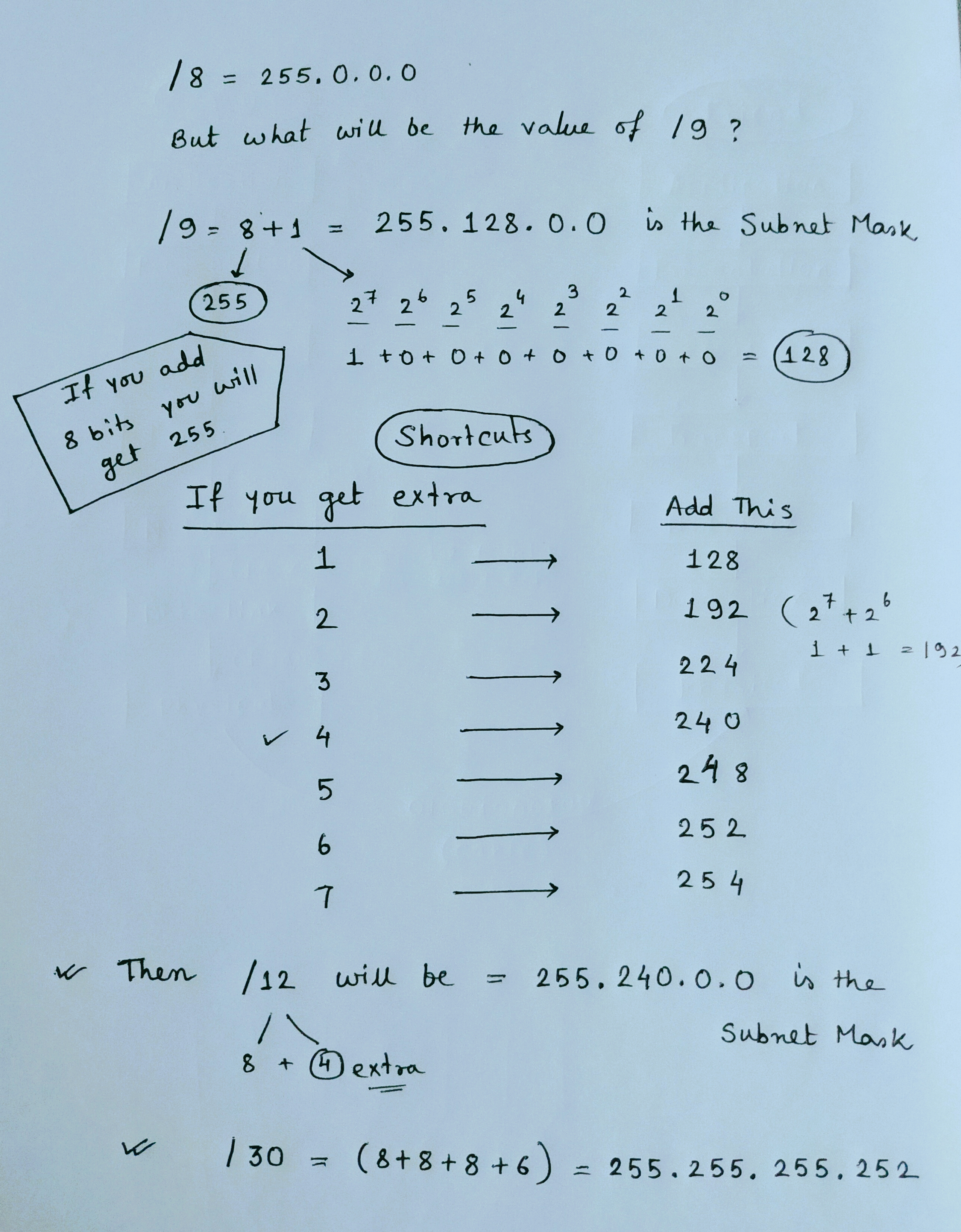
Subnet Mask represents the network bits. Computer needs extra information that computer belongs to which network. Subnet mask is represented by / value.
/8 = 255.0.0.0 means it represents 8 bits of an IP address and if you add all 8 bits like (2^7+2^6+2^5+2^4+2^3+2^2+2^1+2^0 = 255). Each octet can vary from 0-255.
Computer can't understand the IP address directly. So via subnet mask, the computer can understand the IP address because subnet deals with bits. Now we know that for class A IP address only first octet will be checked for Network ID and similarly for class B first 2 octets and for class C first three octets. e.g :- As This IP 123.34.0.1/8 belongs to class A so via its subnet mask 255.0.0.0 computer can recognize that this is a class A IP address.
-- DEFAULT SUBNET MASK --
Class A - 255.0.0.0 as it checks for first octet or 8 bits
Class B - 255.255.0.0 as it checks for first two octets or 16 bits
Class C - 255.255.255.0 as it checks for first three octets or 24 bits
Network Utilities #
-
Ping
Ping (Packet Internet Gropers) is a basic internet program which is used to check the connectivity between two or more devices. Suppose, in device A if you are getting reply from device B that means both the devices are connected with each other, and they can share any files now. Ping actually sends some packets of some bytes of size (you can set manually) to another device which can be a server also and then if that second device or server send back response to you then that two devices are connected with each other. Here
google.comis the second device (server).What is TTL in above picture?
TTL means Time-To-Live is a value for the period of time that a packet should exist on a network before being dropped or discarded. e.g:- TTL= 111 means after checking 111 routers over the internet if that IP ping 142.250.194.14 is not found on internet then that packet will be dropped, and you can see that dropped packets in result.
**Hope this blog will help you!**👍
Get new posts in your inbox.
Spotted a typo or want to improve this post? Edit on GitHub →